LaserDistanceDIN: Difference between revisions
| (4 intermediate revisions by the same user not shown) | |||
| Line 1: | Line 1: | ||
[[File:LaserDistanceDINMain.webp|alt=LaserDistanceDIN Main|thumb|LaserDistanceDIN Main]] |
|||
== Overview == |
== Overview == |
||
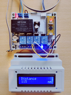
LaserDistanceDIN is a DIN rail mount controller and measurement device. Four relays can be used to control any process and two alarming sources of information about a critical value. It uses laser light to measure the distance between the sensor and the object. The measurement is based on the ToF (time of flight) of light from the source (sensor) and is the reflection (object). |
LaserDistanceDIN is a DIN rail mount controller and measurement device. Four relays can be used to control any process and two alarming sources of information about a critical value. It uses laser light to measure the distance between the sensor and the object. The measurement is based on the ToF (time of flight) of light from the source (sensor) and is the reflection (object). |
||
| Line 11: | Line 13: | ||
=== Powering === |
=== Powering === |
||
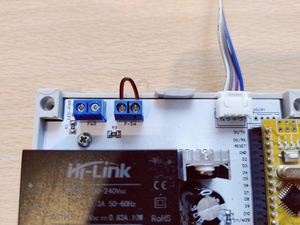
LaserDistanceDIN uses 220VAC for powering. The power connector is on the left upper corner, marked on the PCB with '''"PWR".''' Next to the powering terminal screw, is the switching port, marked on the PCB with '''"P-SW"'''. It interrupts the powering of the device. If You need this function, just install an interrupter for 220VAC. In case You don't need this function, just shortcut it, because if You remove the wire on that connector, the device still stays not powered. For the wiring, use 1.5mm<sup>2</sup> cable, the maximal current that a device need is under 300mA at 220VAC. |
LaserDistanceDIN uses 220VAC for powering. The power connector is on the left upper corner, marked on the PCB with '''"PWR".''' Next to the powering terminal screw, is the switching port, marked on the PCB with '''"P-SW"'''. It interrupts the powering of the device. If You need this function, just install an interrupter for 220VAC. In case You don't need this function, just shortcut it, because if You remove the wire on that connector, the device still stays not powered. For the wiring, use 1.5mm<sup>2</sup> cable, the maximal current that a device need is under 300mA at 220VAC. |
||
[[File:LaserDistanceDIN Power.webp|alt=LaserDistanceDIN Power|center|thumb|LaserDistanceDIN Power]] |
|||
=== Sensor installation === |
=== Sensor installation === |
||
| Line 18: | Line 21: | ||
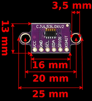
The sensor is connected with a JST-XH 4-pin connector to the PCB, over one 1-meter-long flat cable. |
The sensor is connected with a JST-XH 4-pin connector to the PCB, over one 1-meter-long flat cable. |
||
[[File:VL53L0X.webp|alt=LaserDistanceDIN Sensor VL53L0X|center|thumb|200x200px|LaserDistanceDIN Sensor VL53L0X]] |
|||
=== Relay installation === |
=== Relay installation === |
||
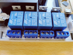
The device has four independent relays. All relays can be configured to be triggered or disabled by software. The maximal current by short intervals that can be switched is 10A by 220VAC. Continuous powering (more than 10 minutes or more than 6A) is recommended to use a contractor and to power the contractor from the relays. Continuously usage of relays over 10A for a long time can produce overheating and damage the device. |
[[File:LaserDistanceDINRelays.webp|alt=LaserDistanceDIN Relays|thumb|241x241px|LaserDistanceDIN Relays]]The device has four independent relays. All relays can be configured to be triggered or disabled by software. The maximal current by short intervals that can be switched is 10A by 220VAC. Continuous powering (more than 10 minutes or more than 6A) is recommended to use a contractor and to power the contractor from the relays. Continuously usage of relays over 10A for a long time can produce overheating and damage the device. |
||
To cable the relays, use 1.5mm<sup>2</sup> wire. On the PCB are tree terminal crews per relay, marked with NC, COM, and NO. NC means Normally Closed, COM is Common and NO is Normally Open. The current state of the replays is presented also with a LED on the PCB surface. |
To cable the relays, use 1.5mm<sup>2</sup> wire. On the PCB are tree terminal crews per relay, marked with NC, COM, and NO. NC means Normally Closed, COM is Common and NO is Normally Open. The current state of the replays is presented also with a LED on the PCB surface. |
||
Latest revision as of 08:06, 25 December 2022
Overview
LaserDistanceDIN is a DIN rail mount controller and measurement device. Four relays can be used to control any process and two alarming sources of information about a critical value. It uses laser light to measure the distance between the sensor and the object. The measurement is based on the ToF (time of flight) of light from the source (sensor) and is the reflection (object).
The measured distances can be shown in millimeters (mm) or inches (inches) in 18 different languages. Also, the device can be used to write measurement results in CSV files. Configuration of a device is made with LaserDistance software.
Hardware installation
The LaserDistanceDIN has to be mounted on a DIN rail. It uses 6 module spaces. Powering off the device can be done with 220VAC or 110VAC. The sensor is connected with a 1-meter-long flat cable to the device.
The sensor has two mounting holes, 20mm distance. By the mounting of the sensor, note that it needs to have a clear view of the measured object. Don't install the device in a humid environment, water tanks, etc. Also, the device must be used indoors and is not made for outdoor usage. Presents of high dust can affect the measurement. The possibility to reflect laser light can affect the measuring range.
Powering
LaserDistanceDIN uses 220VAC for powering. The power connector is on the left upper corner, marked on the PCB with "PWR". Next to the powering terminal screw, is the switching port, marked on the PCB with "P-SW". It interrupts the powering of the device. If You need this function, just install an interrupter for 220VAC. In case You don't need this function, just shortcut it, because if You remove the wire on that connector, the device still stays not powered. For the wiring, use 1.5mm2 cable, the maximal current that a device need is under 300mA at 220VAC.
Sensor installation
Sensing of the distance is done with the Time of Flight technique (ToF), provided by the STMicroelectronics VL53L0X ranging sensor. It has a measuring range of up to 1200mm in ideal condition.
The sensor has to be mounted with two screws to the "zero point", looking at the 90° to the measured object. The sensor uses 5VDC to power and communicate with the I2C protocol.
The sensor is connected with a JST-XH 4-pin connector to the PCB, over one 1-meter-long flat cable.
Relay installation
The device has four independent relays. All relays can be configured to be triggered or disabled by software. The maximal current by short intervals that can be switched is 10A by 220VAC. Continuous powering (more than 10 minutes or more than 6A) is recommended to use a contractor and to power the contractor from the relays. Continuously usage of relays over 10A for a long time can produce overheating and damage the device.
To cable the relays, use 1.5mm2 wire. On the PCB are tree terminal crews per relay, marked with NC, COM, and NO. NC means Normally Closed, COM is Common and NO is Normally Open. The current state of the replays is presented also with a LED on the PCB surface.
Configuration
For the configuration of the device, You must connect the USB cable to the device and a computer with the installed LaserDistance software. At the time of the configuration, the device doesn't need to be powered over 220VAC, but it can be powered.
After You connected the device, start the program, scan for ports, and connect to the port of the LaserDistanceDIN device. If the device was connected, You can see the device picture in the left bottom corner and the measured value in the right bottom corner. The current configuration can be saved to a file for a backup or later changes.
In the LaserDistance software, You can configure multiple parameters, the measurement units, LCD language, alarming, and relay. After You changed any parameter, just save it into the device. You don't need to restart the device after it, the changes will be presented immediately after You save the changes into the device.
Relays and alarms
The relays and the alarm have three possible operational states:
- disabled - there is no action, the control is set to off
- if above - the alarm or the relay will be triggered if the distance rises above the defined value
- if below - the alarm or the relay will be triggered if the distance falls under the defined value
Measurement units
By measuring, the device can present the results in millimeters or inches. Millimeters are SI units while inches are imperial units. The chosen unit will be presented on the LCD panel and in the software window. Also, if You measured a CSV file, it will save in the value that is configured in the device.
Language
The LaserDistanceDIN supports 18 languages: English, German, French, Italian, Portuguese, Spanish, Dutch, Hungarian, Croatian, Slovenian, Serbian, Czech, Slovak, Polish, Danish, Swedish, Norwegian, and Finnish. If You made the changes save them to the device.
Maintenance
The device doesn't require any special maintenance. To have an accurate measurement, check always if the sensor is free of dust. It is covered with dust, You will have false measurements. Is important that no other foreign object has to be between the measuring sensor and the measuring object.
Strong light can damage the sensor, and influence the measurement. Because of this, don't use this device in direct sun illumination or close to any very hot objects (because of infrared lights).
Technical parameters
| Power | 110/220VAC |
|---|---|
| Current | 300mA at 220VAC |
| Size | 107 X 89 X 82mm |
| Sensor | VL53L0X Time-of-Flight (ToF) laser-ranging |
| Range | 10 - 1200 mm |
| Resolution | 1mm |
| Accuracy | ±3% |
| Sensor cable length | 1 meter |
| Relay current | maximal 10A at 220AC |


