BasicTimer4X: Difference between revisions
| (23 intermediate revisions by the same user not shown) | |||
| Line 2: | Line 2: | ||
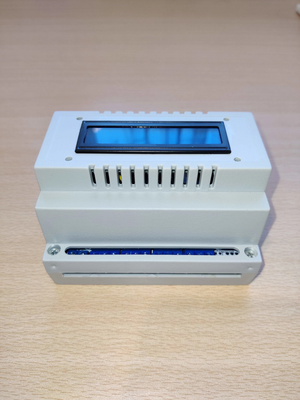
BasicTimer4X is designed to provide a simple solution for timing and triggering. It contains a DIN rail mounted hardware and a software for configuration. Is powered with 220VAC, but can be also powered over a USB port. |
BasicTimer4X is designed to provide a simple solution for timing and triggering. It contains a DIN rail mounted hardware and a software for configuration. Is powered with 220VAC, but can be also powered over a USB port. |
||
4 relays can be configured in two modes, independent and cyclic. Each relay can be configured separately for timing or can be disabled. On the LCD You can read the current state of any relay (On or |
4 relays can be configured in two modes, independent and cyclic. Each relay can be configured separately for timing or can be disabled. On the LCD You can read the current state of any relay (On, Off or Out). |
||
== Specification == |
== Specification == |
||
[[File:Basictimer4x-front.webp|alt=BasicTimer 4X|thumb|BasicTimer 4X]] |
|||
{| class="wikitable" |
{| class="wikitable" |
||
|+Specification table |
|+Specification table |
||
| Line 40: | Line 41: | ||
== Hardware == |
== Hardware == |
||
=== Installation === |
|||
[[File:Basictimer4x-power-switch.webp|alt=BasicTimer 4X Power and Switch connectors|thumb|BasicTimer 4X Power and Switch connectors]] |
|||
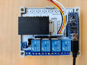
The device have to be installed on DIN rails in electrical boxes. It have a dimension of 89mm X 107mm X 65mm, on a rail it will use 6 modules place. By installing leave always more cable, for a later manipulation. On a front side are 4 screws. Remove it and open a box. Detach the LCD cable from the PCB. Mount the bottom side on DIN rail and connect the wires to the relays. Please note that a relays have 3 pins (NO - Normally open, CO - Common and NC - Normally closed, from left to right). At this time, connect the USB mini cable to the device and configure it. Try the relay behavior, the timing and the switching function. On the PC, in the BasicTimer4X software, You can see which relays are opened. If all the functions working as needed, remove the USB mini cable and connect the LCD cable to the PCB. Connect the 220VAC power supply, and check again is everything working. Close the box with a screws. |
|||
=== Power supply === |
|||
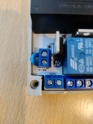
BasicTimer4X uses a 2A 5VDC to powering the MCU, relays and the LCD. The PSU don't need a high current, so You can use a 1.5mm<sup>2</sup> wire for power and for switching. On the PCB is installed a switch port. It can be used to mount a reset button. By default, is shorted. |
|||
If You need a switching of the device, You can use any switch to cut of the power on the switching port. Please note that a switching port uses 220VAC. |
|||
Because the device has a low power composition, You can use it with a 5VDC power over a USB connector on the MCU (USB micro connector). This connector is used to program the device but can be also used to power it. Please note, that in a case You use the USB port for powering, You need a 2A 5VDC USB connector that is used for phone charging. |
|||
For higher stability, we discourage You to use the USB power, but if You have no 220VDC, it can be powered over USB but is less stable. |
|||
=== Relays === |
|||
[[File:Basictimer4x-relays-numbered.webp|alt=BasicTimer 4X Relays|thumb|BasicTimer 4X Relays]] |
|||
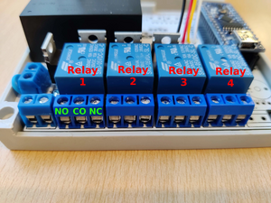
Relays are the most important part of the device. With a 4 independent relays, You can switch 4 devices, like, pumps, valves, etc. The relays can be used by load under 5A at 220VAC. Any higher load need to be done with contactor. |
|||
The relays have 3 pins (from left to right): |
|||
* NO - Normally open |
|||
* CO - Common |
|||
* NC - Normally closed |
|||
Depending of the task, You can wire it to achieve the wished behavior. |
|||
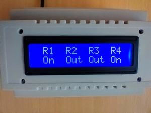
The relay status can be read from LCD and with the BasicTimer4X. On the LCD is in the upper line written the relay number (R1 R2 R3 R4) and under the relay number is presented the current status of the relay (On, Off or Out). With the BasicTimer4X software, You need first to be connected to the device, and the relay status will be presented in the lower left corner of the program. |
|||
=== LCD === |
|||
[[File:Basictimer4x-lcd.webp|alt=BasicTimer 4X LCD|thumb|BasicTimer 4X LCD]] |
|||
To be able seeing the current state of any relay or from the whole device, we have installed one LCD. It have two lines, on the upper line is the relay number (R1 R2 R3 R4) and on the lower line is the relay status (On, Off or Out). The LCD is connected to the main PCB with a connector that can be detached in the time of service. The device will working no matter if the LCD is connected or not. If the LCD is disconnected, You can use the program BasicTimer4X to see which relay is on. |
|||
Contrast of the LCD can be adjusted with the trimer on the back side of the LCD. |
|||
=== USB connection === |
|||
With a USB connection, You can power up the device, if You have no 220VAC and You can configure the parameters. Connecting will be done with a USB mini cable (the cable will be NOT delivered in a package). Connect the USB to the device and to PC. Wait 10 seconds that a device boot up and start the BasicTimer4X program to made a configuration. |
|||
[[File:Basictimer4x-inside.webp|alt=BasicTimer 4X USB and LCD connectors|center|thumb|BasicTimer 4X USB and LCD connectors]] |
|||
== Software == |
|||
{| class="wikitable" align="right" |
|||
! colspan="2" |[[File:BasicTimer4X-software.webp|alt=Main screen of BasicTimerX4|center|thumb|300x300px|Main screen of BasicTimerX4]] |
|||
|- |
|||
|Developer |
|||
| RAPMAS |
|||
|- |
|||
|Written in |
|||
| C# |
|||
|- |
|||
|Operating system |
|||
| Windows |
|||
|- |
|||
|Size |
|||
|4MB |
|||
|- |
|||
|Download |
|||
|[https://download.rapmas.com/BasicTimer_4X.exe BasicTimer_4X.exe] |
|||
|- |
|||
|Licence |
|||
|Freeware |
|||
|- |
|||
|Website |
|||
|https://www.rapmas.com/BasicTimer4X |
|||
|}The BasicTimer4X is designed to configure and read the status of the hardware. Communication between the software and hardware is done with the integrated USB to Serial TTL over a USB micro cable. It supports 16 languages: English, German, French, Spanish, Dutch, Hungarian, Croatian, Slovenian, Serbian (Latin), Czech, Slovakian, Polish, Danish, Swedish, Norwegian, and Finnish. |
|||
=== Installation === |
|||
The installer can be [https://download.rapmas.com/BasicTimer_4X.exe downloaded online]. After starting the install process, You will be asked to choose the language of the installation. Please note that a chosen language will be the default language at the first start of the program. It can be changed later at any time. Executable and the supporting files will be installed (by default) to the Program Files folder, and can be started from the Start menu. Also in the Start menu can be accessed Uninstaller. |
|||
=== Configuration === |
|||
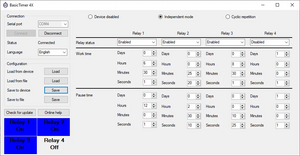
Connect the device to the USB port and wait 10 seconds, to boot up the device. After starting the program, You can see the main configuration window. It is used to configure a device, read the relay staus and to save the configurations into the device, and also file. |
|||
In the upper right corner is the Connection group box. You must choose the correct Serial port. After this, You have to click on the Connect button. If the Serial port was correct the Status message will be changed to Connected. If You have more serial devices connected, check one by one which is from the device. Under the Status box can be selected the program language, after a change, the program will restart automatically in a new language. In the left bottom corner will be presented the the relay status in a blue box with a white text, if a relay is active, or opposite if is inactive. |
|||
Configuration can be loaded and saved from a device and from a file. To read the initial configuration from the device, click to Load button close to "Load from device". It will read out the configuration, if the device is connected before. The same can be done with a previously stored file, that contains the configuration parameters. Saving the configuration can be done by clicking on the Save button, close to the destination of saving (Device or File). Please note that a program will check is the input data for any parameter is correct or not. In a case of incorrect value, it will not write the configuration to the device or file. |
|||
=== Relay status === |
|||
If the device is connected to the program, You can read the current status of any relay, same as on the LCD screen. In lower left corner will be a square with 4 parcels, for each relay. The relay name is on the uppers side of the square and the current status of the relay (On or Off) is above the relay number. With this function You can always track the behavior of relays without seeing it on the LCD screen. |
|||
=== Device modes === |
|||
The device have 3 main modes: Device disabled, Independent mode and Cyclic repetition . The modes can be changed "on the fly". |
|||
==== Device disabled ==== |
|||
In this mode, the relays are reactivated. Is used to check the wiring of the cables, stopping the device in case of emergency or in any other case where You need to stop the normal working of the device. In this mode, the device is normally powered, the LCD shows "Out Out Out Out", and in BasicTimer4X software for relay status is written "Off". Please not that a "Device disabled" mode don't cut the 220VAC from PSU (Power Supply Unit) to MCU (Micro Controller Unit) device, it just stop activating of relays and deactivate the already activated relays. |
|||
==== Independent mode ==== |
|||
This mode is used in most situation where is needed an relay independent behavior. In this mode, each relay will be activated at the start, will worked until the "Work time" is done, the relay will be aftermath deactivated for a "Pause time". If the "Pause time" is over, the relay will start again over in "Work time". In this mode, Relay 1 will work in own cycles of working and pause time, independent of the Relay 2 or Relay 4. In this mode, at start You will have all the enabled relays active, but later the number of active relays will be changed according to the defined cycles for each relay. |
|||
Example 1: |
|||
Garden pump 1 will start and work for 2 hours. After this 2 hours of work, it will pause for 4 hours. After 4 hours of pause, the pump will start over and work in cycles of "2 hour work - 4 hour pause". |
|||
Garden pump 2 will start and work for 1 hour. After this 1 hour of work, it will pause for 6 hours. After 6 hours of pause, the pump will start over and work in cycles of "1 hour work - 6 hour pause". |
|||
Garden pump 3 is disabled because of pipe replacement, it will not work. |
|||
Garden pump 4 will start and work for 3 hours. After this 3 hours of work, it will pause for 21 hours. After 21 hours of pause, the pump will start over and work in cycles of "3 hour work - 21 hour pause". |
|||
All the 3 enabled pumps (1, 2 and 4) will start at same time, by starting the device, but it cycles are independent from each other. Relay 2 will not wait that Relay 1 finish his own cycle. |
|||
==== Cyclic repetition ==== |
|||
This mode is made to create working cycles where after Relay 1 finish is working-pause cycle, start the Relay 2. Relay 2 will not start until Relay 1 is finished with his pause. In this mode, You can have only 1 relay active at same time. One whole cycle looks: |
|||
Relay 1 work <big>⇒</big> Relay 1 pause <big>⇒</big> Relay 2 wor<big>k ⇒</big> Relay 2 pause <big>⇒</big> Relay 3 work <big>⇒</big> Relay 3 pause <big>⇒</big> Relay 4 work <big>⇒</big> Relay 4 pause |
|||
After the Relay 4 pause is over, the device will roll over to begin and will start with Relay 1 work cycle. |
|||
Example 2: |
|||
Garden pump 1 will start and work for 2 hours. After this 2 hours of work, it will pause for 4 hours. After 4 hours of pause, the pump will stay off. |
|||
Garden pump 2 will start after the garden pump 1 pause time is finished (4 hours). It will works for 1 hour. After this 1 hour of work, it will pause for 6 hours. After 6 hours of pause, the pump will stay off. |
|||
Garden pump 3 is disabled because of pipe replacement, it will not work, the device will not wait to any timing of the pump 3. |
|||
Garden pump 4 will start after garden pump 2 pause time is finished (6 hours), because the pump 3 was disabled and will work for 3 hours. After this 3 hours of work, it will pause for 21 hours. After 21 hours of pause, the pump will stay off. |
|||
Because the cycle is finished, after the pause of 21 hours for pump 4, the device will begin with with pump 1 the new cycle over. To make a total cycle of all 4 relays it needs 37 hours (2+4+1+6+3+21). |
|||
Important is to have minimal 2 relays enabled to have a cyclic mode. If You disable 3 relays (no mater which 3) the cyclic mode will not work. |
|||
=== Relay configuration === |
|||
Each relay can be configured separately. In the main configuration window is the relay number (Relay 1, Relay 2, etc). All the configuration parameters for the relay is made under the relay number, in order: Relay status, Working time and Pause time. |
|||
==== Relay status ==== |
|||
With the Relay status can be a relay enabled or disabled. If the relay is enabled, the corresponding cycles of the working and pause time will be executed. If the relay is disabled, the device will ignore the relay timing for work and pause time, it will leave the relay inactive. This parameter is used if You need maintain the device connected to the relay, but You wish not detach the cables from the connector. Also in an emergency case, You can disable only that one relay, leaving the other relays in function. In a Cyclic repetition mode You must have minimal 2 enabled relays. In a independent mode minimal 1 enabled relays. |
|||
==== Work time ==== |
|||
This parameter is made to define how long have a relay to work, before it goes to pause. You can define the interval in Days, Hours, Minutes and Seconds. The timer must have always minimal 1 second time. In this period is the relay activated and on LCD is a message "On" under the relay number. |
|||
==== Pause time ==== |
|||
Pause times define how long have a relay to be switched off. This happens always after a work time, and in pause time cycle is the relay always off. The timer must have always minimal 1 second time in this mode. In this period is the relay not active, and on LCD is a message "Off" under the relay number. |
|||
Latest revision as of 17:38, 20 January 2022
Description
BasicTimer4X is designed to provide a simple solution for timing and triggering. It contains a DIN rail mounted hardware and a software for configuration. Is powered with 220VAC, but can be also powered over a USB port.
4 relays can be configured in two modes, independent and cyclic. Each relay can be configured separately for timing or can be disabled. On the LCD You can read the current state of any relay (On, Off or Out).
Specification
| Parameter | Value |
|---|---|
| Hardware | |
| Power | 220 VAC or 5 VDC over USB |
| Minimal timing interval | 1 second |
| Maximal timing interval | 1 year |
| LCD | 2.56" with blue background light |
| Relay | 4 independent relays, maximal load 2A at 220VAC |
| Software | |
| Operation system | Windows 8 and Windows 10 |
| Communication | Serial over USB, TTL on device |
| Software functions | Configuration and device status |
Hardware
Installation
The device have to be installed on DIN rails in electrical boxes. It have a dimension of 89mm X 107mm X 65mm, on a rail it will use 6 modules place. By installing leave always more cable, for a later manipulation. On a front side are 4 screws. Remove it and open a box. Detach the LCD cable from the PCB. Mount the bottom side on DIN rail and connect the wires to the relays. Please note that a relays have 3 pins (NO - Normally open, CO - Common and NC - Normally closed, from left to right). At this time, connect the USB mini cable to the device and configure it. Try the relay behavior, the timing and the switching function. On the PC, in the BasicTimer4X software, You can see which relays are opened. If all the functions working as needed, remove the USB mini cable and connect the LCD cable to the PCB. Connect the 220VAC power supply, and check again is everything working. Close the box with a screws.
Power supply
BasicTimer4X uses a 2A 5VDC to powering the MCU, relays and the LCD. The PSU don't need a high current, so You can use a 1.5mm2 wire for power and for switching. On the PCB is installed a switch port. It can be used to mount a reset button. By default, is shorted.
If You need a switching of the device, You can use any switch to cut of the power on the switching port. Please note that a switching port uses 220VAC.
Because the device has a low power composition, You can use it with a 5VDC power over a USB connector on the MCU (USB micro connector). This connector is used to program the device but can be also used to power it. Please note, that in a case You use the USB port for powering, You need a 2A 5VDC USB connector that is used for phone charging.
For higher stability, we discourage You to use the USB power, but if You have no 220VDC, it can be powered over USB but is less stable.
Relays
Relays are the most important part of the device. With a 4 independent relays, You can switch 4 devices, like, pumps, valves, etc. The relays can be used by load under 5A at 220VAC. Any higher load need to be done with contactor.
The relays have 3 pins (from left to right):
- NO - Normally open
- CO - Common
- NC - Normally closed
Depending of the task, You can wire it to achieve the wished behavior.
The relay status can be read from LCD and with the BasicTimer4X. On the LCD is in the upper line written the relay number (R1 R2 R3 R4) and under the relay number is presented the current status of the relay (On, Off or Out). With the BasicTimer4X software, You need first to be connected to the device, and the relay status will be presented in the lower left corner of the program.
LCD
To be able seeing the current state of any relay or from the whole device, we have installed one LCD. It have two lines, on the upper line is the relay number (R1 R2 R3 R4) and on the lower line is the relay status (On, Off or Out). The LCD is connected to the main PCB with a connector that can be detached in the time of service. The device will working no matter if the LCD is connected or not. If the LCD is disconnected, You can use the program BasicTimer4X to see which relay is on.
Contrast of the LCD can be adjusted with the trimer on the back side of the LCD.
USB connection
With a USB connection, You can power up the device, if You have no 220VAC and You can configure the parameters. Connecting will be done with a USB mini cable (the cable will be NOT delivered in a package). Connect the USB to the device and to PC. Wait 10 seconds that a device boot up and start the BasicTimer4X program to made a configuration.
Software
| Developer | RAPMAS |
| Written in | C# |
| Operating system | Windows |
| Size | 4MB |
| Download | BasicTimer_4X.exe |
| Licence | Freeware |
| Website | https://www.rapmas.com/BasicTimer4X |
The BasicTimer4X is designed to configure and read the status of the hardware. Communication between the software and hardware is done with the integrated USB to Serial TTL over a USB micro cable. It supports 16 languages: English, German, French, Spanish, Dutch, Hungarian, Croatian, Slovenian, Serbian (Latin), Czech, Slovakian, Polish, Danish, Swedish, Norwegian, and Finnish.
Installation
The installer can be downloaded online. After starting the install process, You will be asked to choose the language of the installation. Please note that a chosen language will be the default language at the first start of the program. It can be changed later at any time. Executable and the supporting files will be installed (by default) to the Program Files folder, and can be started from the Start menu. Also in the Start menu can be accessed Uninstaller.
Configuration
Connect the device to the USB port and wait 10 seconds, to boot up the device. After starting the program, You can see the main configuration window. It is used to configure a device, read the relay staus and to save the configurations into the device, and also file.
In the upper right corner is the Connection group box. You must choose the correct Serial port. After this, You have to click on the Connect button. If the Serial port was correct the Status message will be changed to Connected. If You have more serial devices connected, check one by one which is from the device. Under the Status box can be selected the program language, after a change, the program will restart automatically in a new language. In the left bottom corner will be presented the the relay status in a blue box with a white text, if a relay is active, or opposite if is inactive.
Configuration can be loaded and saved from a device and from a file. To read the initial configuration from the device, click to Load button close to "Load from device". It will read out the configuration, if the device is connected before. The same can be done with a previously stored file, that contains the configuration parameters. Saving the configuration can be done by clicking on the Save button, close to the destination of saving (Device or File). Please note that a program will check is the input data for any parameter is correct or not. In a case of incorrect value, it will not write the configuration to the device or file.
Relay status
If the device is connected to the program, You can read the current status of any relay, same as on the LCD screen. In lower left corner will be a square with 4 parcels, for each relay. The relay name is on the uppers side of the square and the current status of the relay (On or Off) is above the relay number. With this function You can always track the behavior of relays without seeing it on the LCD screen.
Device modes
The device have 3 main modes: Device disabled, Independent mode and Cyclic repetition . The modes can be changed "on the fly".
Device disabled
In this mode, the relays are reactivated. Is used to check the wiring of the cables, stopping the device in case of emergency or in any other case where You need to stop the normal working of the device. In this mode, the device is normally powered, the LCD shows "Out Out Out Out", and in BasicTimer4X software for relay status is written "Off". Please not that a "Device disabled" mode don't cut the 220VAC from PSU (Power Supply Unit) to MCU (Micro Controller Unit) device, it just stop activating of relays and deactivate the already activated relays.
Independent mode
This mode is used in most situation where is needed an relay independent behavior. In this mode, each relay will be activated at the start, will worked until the "Work time" is done, the relay will be aftermath deactivated for a "Pause time". If the "Pause time" is over, the relay will start again over in "Work time". In this mode, Relay 1 will work in own cycles of working and pause time, independent of the Relay 2 or Relay 4. In this mode, at start You will have all the enabled relays active, but later the number of active relays will be changed according to the defined cycles for each relay.
Example 1:
Garden pump 1 will start and work for 2 hours. After this 2 hours of work, it will pause for 4 hours. After 4 hours of pause, the pump will start over and work in cycles of "2 hour work - 4 hour pause".
Garden pump 2 will start and work for 1 hour. After this 1 hour of work, it will pause for 6 hours. After 6 hours of pause, the pump will start over and work in cycles of "1 hour work - 6 hour pause".
Garden pump 3 is disabled because of pipe replacement, it will not work.
Garden pump 4 will start and work for 3 hours. After this 3 hours of work, it will pause for 21 hours. After 21 hours of pause, the pump will start over and work in cycles of "3 hour work - 21 hour pause".
All the 3 enabled pumps (1, 2 and 4) will start at same time, by starting the device, but it cycles are independent from each other. Relay 2 will not wait that Relay 1 finish his own cycle.
Cyclic repetition
This mode is made to create working cycles where after Relay 1 finish is working-pause cycle, start the Relay 2. Relay 2 will not start until Relay 1 is finished with his pause. In this mode, You can have only 1 relay active at same time. One whole cycle looks:
Relay 1 work ⇒ Relay 1 pause ⇒ Relay 2 work ⇒ Relay 2 pause ⇒ Relay 3 work ⇒ Relay 3 pause ⇒ Relay 4 work ⇒ Relay 4 pause
After the Relay 4 pause is over, the device will roll over to begin and will start with Relay 1 work cycle.
Example 2:
Garden pump 1 will start and work for 2 hours. After this 2 hours of work, it will pause for 4 hours. After 4 hours of pause, the pump will stay off.
Garden pump 2 will start after the garden pump 1 pause time is finished (4 hours). It will works for 1 hour. After this 1 hour of work, it will pause for 6 hours. After 6 hours of pause, the pump will stay off.
Garden pump 3 is disabled because of pipe replacement, it will not work, the device will not wait to any timing of the pump 3.
Garden pump 4 will start after garden pump 2 pause time is finished (6 hours), because the pump 3 was disabled and will work for 3 hours. After this 3 hours of work, it will pause for 21 hours. After 21 hours of pause, the pump will stay off.
Because the cycle is finished, after the pause of 21 hours for pump 4, the device will begin with with pump 1 the new cycle over. To make a total cycle of all 4 relays it needs 37 hours (2+4+1+6+3+21).
Important is to have minimal 2 relays enabled to have a cyclic mode. If You disable 3 relays (no mater which 3) the cyclic mode will not work.
Relay configuration
Each relay can be configured separately. In the main configuration window is the relay number (Relay 1, Relay 2, etc). All the configuration parameters for the relay is made under the relay number, in order: Relay status, Working time and Pause time.
Relay status
With the Relay status can be a relay enabled or disabled. If the relay is enabled, the corresponding cycles of the working and pause time will be executed. If the relay is disabled, the device will ignore the relay timing for work and pause time, it will leave the relay inactive. This parameter is used if You need maintain the device connected to the relay, but You wish not detach the cables from the connector. Also in an emergency case, You can disable only that one relay, leaving the other relays in function. In a Cyclic repetition mode You must have minimal 2 enabled relays. In a independent mode minimal 1 enabled relays.
Work time
This parameter is made to define how long have a relay to work, before it goes to pause. You can define the interval in Days, Hours, Minutes and Seconds. The timer must have always minimal 1 second time. In this period is the relay activated and on LCD is a message "On" under the relay number.
Pause time
Pause times define how long have a relay to be switched off. This happens always after a work time, and in pause time cycle is the relay always off. The timer must have always minimal 1 second time in this mode. In this period is the relay not active, and on LCD is a message "Off" under the relay number.
