HydroLevelControl
Description
HydroLevelControl is a bundle of hardware and software designed to measure, present and control the level of fluids. Measurement is based on the hydrostatic pressure provided by the fluid above the pressure sensor. The measured pressure value is converted to a requested data format, according to inserted data, like fluid density, reservoir surface, etc. The measured value can be used to activate the visual alarm (blinking LCD display), sound alarm, and two relays. All this can be configured independently.
Take care that this device can be used only on atmospheric pressure. Installation in an over or under pressured environment can permanently damage the sensor and the device! Have to be used only for water, not suitable for petrol, gasoline, alcohol, and other organic solvents.
Background
The device has a pressure sensor, actually a pressure transducer, that is powered with 5 VDC. Depending on the pressure, it produces a different voltage on output that is measured and converted to pressure. Based on the fluid density, is possible to calculate the height of the fluid above the sensor. With the known height and the reservoir surface, can be calculated the volume and the mass of the fluid.
Specification

| Parameter | Value |
|---|---|
| Hardware | |
| Power | 220 VAC or 5 VDC over USB |
| Sensor type | Pressure transducer, 5 VDC |
| Sensor range | 5 - 15 psi |
| Sensor offset | 0.5 VDC (at 0 pressure) to 4.5 VDC (at maximal pressure) |
| Inlet size | 1/8”-27 NPT |
| LCD | 2.9" with blue background light |
| Relay | 2 independent relays, maximal load 2A at 220VAC |
| Software | |
| Operation system | Windows 8 and Windows 10 |
| Communication | Serial over USB, TTL on device |
| Software functions | Configuration and measurement |
Hardware
Installation
The device has to be installed on a panel in a hole with a dimension of 97 x 72mm. All the cables from the AC power, reset switch and sensor need to be connected to the device before mounting. Don't use this device outdoor or in a harsh environment. The sensor can be used in a wet environment but the LCD is not. Also, please take care that a device is powered with 220VAC. Before You mount the device in a hole, connect all the cables and connect the sensor and test the device. Please leave always enough cable to manipulate the panel by mounting.
Power supply

HydroLevelControl uses 100-240VAC for powering. The PSU (Power Supply Unit) of a device provides 5VDC 2A for the MCU (Main Control Unit), LCD, relays, and the rest of the electronics. On the backside of the device is on the outer side the screw connector to put the AC wire. The device doesn't need a high current, so You can use a 1.5mm2 wire for power and for switching.
Switching the device On/Off or to restart, can be done with a second screw connector, close to the power connector. This can be done with any switch. On this connector is the power line from the main power input to the PSU interrupted over the connector. As You can see in the picture, here is a simple wire that shorts this switch, but if You need a switching, just remove the blue wire and connect Your own switch.
Because the device has a low power composition, You can use it with a 5VDC power over a USB connector on the MCU (USB micro connector). This connector is used to program the device but can be also used to power it. Please note, that in a case You use the USB port for powering, You need a 2A 5VDC USB connector that is used for phone charging.
For higher stability, we discourage You to use the USB power, but if You have no 220VDC, it can be powered over USB but is less stable and less precise.
Relays

The most important part of the device is the controlling function. To be able to start pumps, valves, compressors, and other high load devices, we have integrated two relays. Both of them can be controlled independently. Triggering of relays can be configured in the configuration software to one of the next modes:
- Off - The relay is not used
- If above value - The relay will be triggered, if the level rise above the defined value
- If below value - The relay will be triggered, if the level falls under the defined value
Each relay has its own isolated connection screw. In the picture, You can see the wiring diagram scheme, where NO mean normally open, CO common, and NC is normally closed.
The relays can switch up to 10A for a short time, but we recommend using the relays only to trigger a separate contactor.
LCD and sound alarms
With the alarm function, You can be always warned if the level of the fluid rises or fall under a predefined level. Both parameters can be configured individually and independently in software.
Visual alarm is presented by fast fading of the LCD and return to maximal brightness. This behavior is similar to blinking, but a bit slower. The main goal is to see that an alarming level is reached, even from a bigger distance. Also, if You have multiple installed devices, You can easily see which one is aimed.
Sound alarm is made to have audio information if the alarming level is reached. The beeper produces a tone with one second, and after it makes a pause from one second, then repeat. Please note that this alarming function can be used only in a quiet environment. Also, if You have multiple devices, the sound alarm is not the best solution to distinguish which one is aimed.
The best practice is to set up the visual alarm and the sound alarm together. With this, You will be warned even if You don't look at the device and if You have multiple devices, You will see which one is armed. If You need only to monitor the level, without the alarming function, You can disable this future by the Visual alarm mode and Speaker alarm mode in HydroLevelControl Software.
Sensor

The device uses a pressure transducer to provide information about the hydrostatic pressure generated by the fluid in a reservoir.
These sensors use 5VDC and have an offset of 0.5VDC. It means that a pressure transducer has a linear range beginning at the 0 pressure until the declared maximal pressure in a range of 0.5V at zero pressure and 4.5V at maximal pressure.
The Inlet of a sensor is made with the thread of 1/8" -27 NTP and it needs to be mounted at the lowest point of a reservoir. Please note that a sensor will measure the level from the mount point. The highest working temperature is 60 ℃. It can be used to measure water level, don't use it to measure petrol, gasoline oil, and another organic dilutes because it can permanently damage the sensor. Don't overload the sensor. To prevent an overload, always bay a sensor, where the highest possible level of the reservoir is about 80% of the sensor measurement range.
| Sensor (PSI) | Maximal water level (meter) |
|---|---|
| 5 | 3.5 |
| 15 | 10.5 |
| 30 | 21 |

By the mounting in a reservoir take care not to build siphons. To achieve this, mount the sensor in a hole that is pointing upwards so that no air bauble can be closed in a sensor inlet. Closed air in a sensor will produce a slower response and lower precision of a sensor. This effect is increased at higher temperatures. To prevent overload of the sensor, You can place a valve between the sensor and a reservoir, so that You can close this valve by cleaning the reservoir with overpressured water.
Regardless of the sensor value, it must be connected to the mainboard. Is done with a 4 pin connector (JST XH2.54). By mounting the sensor, leave enough cable length for manipulation by installing and removing the panel from the hole. From the PCB side, the connector is placed close to a buzzer, is white-colored.
We send the sensor with a soldered connector on a 1m cable. In case You need a longer cable, You can unsolder the cable and use a longer cable. In a real industrial environment, we have successfully installed a dozen systems with more than 10 meters of cable. By this, we used always a 3 wire 1.5mm2 cable, don't use cables with smaller diameters.
The pinout of the sensor and the cable is the following:
- Red - +5VDC - is used to powering the sensor, positive pole
- Black - -5VDC - is used to powering the sensor, negative pole
- Green - signal from the sensor to device, the value depending of the applied pressure
If You wish to have a longer cable, always solder "color to color" on a longer cable, taking care not to change the colors, because it can permanently damage the sensor and the device.
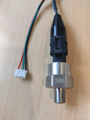
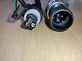
HidroLevelControl 15 PSI sensor with connector
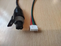
Sensor and JST XH2.54 4 pin connector
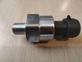
HidroLevelControl 5 PSI sensor side view
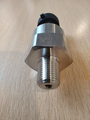
HidroLevelControl 5 PSI sensor frontal view
HidroLevelControl 5 PSI sensor backside view


USB connection
Configuration of the device can be done over the USB connector on the MCU. Also, in the case that You have no 220VAC, You can use this port to power up the device. Please You standard USB mini cable to access the programming port of the device. Inserted the USB port, wait 10 seconds, and start the HydroLevelControl software on Your PC. After You made the necessary changes to the device, just remove the USB cable, is not necessary to restart the device if You change any configuration parameter.

Software
HydroLevelControl software is a program designed to read measured data and configure the hardware. It communicates with a USB to Serial TTL, where the TTL is on the hardware side. The software can be downloaded from this page for free. It supports 16 languages: English, German, French, Spanish, Dutch, Hungarian, Croatian, Slovenian, Serbian (Latin), Czech, Slovakian, Polish, Danish, Swedish, Norwegian, and Finnish.
| Developer | RAPMAS |
| Written in | C# |
| Operating system | Windows |
| Size | 4MB |
| Download | HydroLevel_Control.exe |
| Licence | Freeware |
| Website | www.rapmas.com/HydroLevelControl/ |

Installation
The installer can be downloaded online. After starting the install process, You will be asked to choose the language of the installation. Please note that a chosen language will be the default language at the first start of the program. It can be changed later at any time. Executable and the supporting files will be installed (by default) to the Program Files folder, and can be started from the Start menu. Also in the Start menu can be accessed Uninstaller.
Configuration
Connect the device to the USB port and wait 10 seconds, to boot up the device. After starting the program, You can see the main configuration window. It is used to configure a device, read the measured data and to save the configurations into the device, and also file.
In the upper right corner is the Connection group box. You must choose the correct Serial port. After this, You have to click on the Connect button. If the Serial port was correct the Status message will be changed to Connected. Under the Status box can be selected the program language, after a change, the program will restart automatically in a new language. In the left bottom corner will be presented the measured value with the relay status in a blue box with a white text.
Configuration can be loaded and saved from a device and from a file. To read the initial configuration from the device, click to Load button close to "Load from device". It will read out the configuration. The same can be done with a previously stored file, that contains the configuration parameters. Saving the configuration can be done by clicking on the Save button, close to the destination of saving (Device or File). Please note that a program will check is the input data for any parameter is correct or not. In a case of incorrect value, it will not write the configuration to the device or file.
- Device language is a parameter that changes the information language on the LCD screen. It can be different from Program language.
- Pressure sensor (psi) is a maximal value of the installed pressure sensor. Is engraved on the sensor body (5 psi, 15 psi, etc). Can be only a round number, a decimal number is not allowed.
- Fluid density (kg/m3) can be a round number in kilograms per cubicle meter, without decimal. The density of the clear water is 1000 kg/m3. With a changing of this value, You can fine-tune the reading of the device.
- Reservoir surface (dm2) is used to calculate the volume and weight of the fluids in the reservoir. Is presented as a round number, without a decimal. For example, if the reservoir is round with a diameter of 1.2m, the surface is 3.77 m2 and this is 377 dm2 . If not needed, just write 1 as value.
- Unit is the metric system in which the device will present the measured value. The device supports next values: mm, cm, dm, m, l (liter), kg, m3, and t (ton).
- LCD brightness (0-100) is a parameter to determinate the background illumination of the LCD. At 0 value is the light off, by 100 is the maximal brightness. In a visual alarm mode, the illumination will move from 0 to 100 and back.
- % mode is made to hide the exact data of a height, volume, mass, or any other unit and present it in %. For example, if the reservoir is full at a level of 1600 mm, at the 800mm level the device will show 50.00% instead of the exact level. To use this mode, You must choose the same unit as in the "Unit" parameter above.
- Value at 100% is a round number (decimal not accepted) of the value selected in % mode at maximal value. For example, if You wish to calculate with 250 liters as 100%, write 250 and choose l (liter) for % mode. In this case, at the volume of 100 liters, the device will show 40%.
- Visual alarm mode defines the behavior of the LCD by reaching a defined value. Is useful if the LCD is mounted in a noisy environment or if You have multiple devices installed, and You need to recognize from a bigger distance, which device shows the alarm. It can be set to Off (no action), If above value (trig the visual alarm if the measured value is above the defined) or If below value (trig the visual alarm if the measured value is under the defined).
- Visual alarm value defines a triggering value. It can be a decimal number, like 102.65 . At this value will be the Visual alarm started, if is so configured.
- Speaker alarm mode is the same as the Visual alarm mode, but is used to trigger the onboard speaker. This function is useful in a silent environment to be warned from a bigger distance from the measuring place.
- Speaker alarm value have the same function as the Visual alarm value, but for Speaker.
- Relay 1 and Relay 2 mode have the same behavior as the Visual alarm mode, but for installed relays.
- Relay 1 and Relay 2 value have same function like the Visual alarm value, but for relays.
- Sensor offset value can define the offset of the different sensors. A pressure transducer works in the range from 0 to 5 VDC, but the linear range for measurement is in the range of 0.5 VDC (value at 0 pressure) and 4.5 VDC (value at maximal pressure). The difference is 0.5 VDC, and this is a sensor potential offset. The controller measure the potential of 5VDC in resolution of 1024, so the offset is resolution / working potential * sensor potential offset, practical
1024 / 5VDC * 0.5VDCand this is 102.5, rounded to 103 . Other sensors can have another offset, so read the documentation of the sensor that You use, it is not a sensor provided by us. The delivered sensors have an offset of 103. The offset can be only a round number like 103, not a decimal. - Sensor zero value is used to configure a sensor reading if is no load from the water. With a button Read sensor You can automatically receive this value, but You need to empty the reservoir or remove the sensor from the water. Wait one minute and after this press the Read sensor button. Wait 10 seconds for data, and it will be filled to the field Sensor zero value. Normal values are close to the value of the sensor offset.
- LCD custom text Off/On is a parameter that changes the default text (by the English language: "Measured value") to a Custom text. It is set to on, the text must be entered before saving. Is used to distinguish between multiple installed devices, like "Reservoir 6", or to provide additional information like " Molasses volume". Please note that a text can have maximal 15 alphanumerical characters.